Description
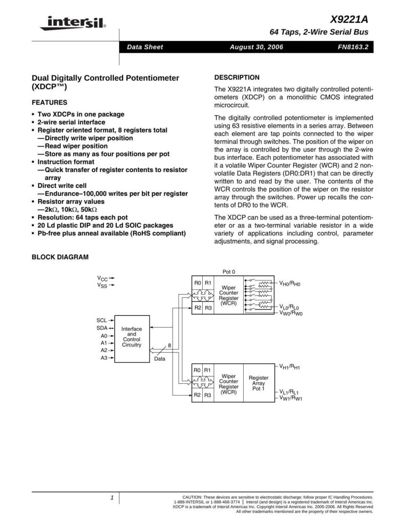
The X9221A from Intersil is a monolithic CMOS integrated microcircuit featuring two digitally controlled potentiometers (XDCPs). Each potentiometer in the package can be engaged for a variety of applications such as control, parameter adjustments, and signal processing. These devices are highly sensitive to electrostatic discharge, thus requiring proper IC handling procedures.
Key Features
Incorporating a 2-wire serial interface that operates with a register-oriented format. There are a total of 8 registers that allow users to directly manipulate the wiper position, read the position back, and store up to four positions per potentiometer. The X9221A supports a quick transfer of register contents to the resistor array and has an endurance of 100,000 writes per bit per register. It also boasts a resolution with 64 taps per pot and possible resistor array values of 2kΩ, 10kΩ, and 50kΩ.
Configuration
The XDCP technology is implemented using a series array of 63 resistive elements, with switches that connect tap points to the wiper terminal. The user is able to control the position of the wiper on the array via the 2-wire bus interface. Each potentiometer has a volatile Wiper Counter Register (WCR) and two non-volatile Data Registers (DR0:DR1), all of which are user-accessible for reading and writing operations.
Register Mechanics
Upon power-up, the contents of DR0 are recalled to the WCR, thus determining the initial position of the wiper. The XDCP can function as either a three-terminal potentiometer or a two-terminal variable resistor.
Packaging
The product is available in 20 Ld plastic DIP and 20 Ld SOIC packages. The X9221A also provides a Pb-free plus anneal option that is RoHS compliant, catering to environmentally conscious applications.
Block Diagram
An included block diagram shows the connection of the two potentiometers (Pot 0 and Pot 1), each with its own Wiper Counter Register (WCR) and connected resistor array. The diagram outlines the essential parts of the potentiometers, including the terminals (Vcc – Vss for power, R0 – R3 for resistive elements, and VHI/RHI, VLO/RLO, and VWO/RWO for variable high, low, and wiper outputs respectively), as well as the interface and control circuitry, consisting of SCL (serial clock line), SDA (serial data), and address lines A0 – A3.
References:
Download: X9221A Dual Digitally Controlled Potentiometer (XDCP) Data Sheet
Chat: Powered By VoiceSphere
Pricing & Distributors: https://www.datasheets360.com/part/detail/x9221aysz/1755276939469692829/

