Overview
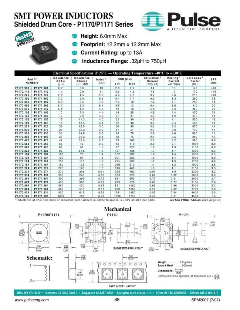
The datasheet details the SMT Power Inductors of the Pulse Shielded Drum Core P11ZO/P1171 Series. These inductors boast a compact design with a maximum height of 6.0mm and a footprint of 12.2mm x 12.2mm. They are capable of handling a current rating of up to 13A and have an inductance range from 0.32μH to 750μH. The series complies with the RoHS directive, indicating that they are free of certain hazardous substances.
Electrical Specifications
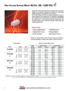
The inductors operate within a temperature range of -40°C to +130°C and exhibit a range of inductance from minimum to maximum specified values across various parts. The datasheet provides a detailed table comparing part numbers with their corresponding Self-Resonance Frequency (SRF), inductance at rated current, DCR, saturation current, heating core loss, and current factor at +40°C. These specifications assist designers in selecting the appropriate inductor based on operating frequency, required inductance, and current handling capabilities.
Suggested Applications and Features
The P11ZO/P1171 series inductors are suggested for various high-performance applications. They are designed for optimal performance in high volt-time (Et) or ripple current scenarios. These inductors come with an optional tape and reel packaging for automated assembly processes. For applications requiring RoHS compliant parts, a “NL” suffix is added to the part number.
Mechanical Characteristics and Testing
The datasheet provides mechanical details and the suggested pad layout for mounting on printed circuit boards (PCBs). It includes the weight in grams and tape & reel dimensions for packaging. Testing is standardly performed at 100kHz and 0.1VAC, and estimated temperature rise is calculated from both copper and core losses in order to ensure the operating temperature remains within the specified range.
Temperature and Loss Estimation
Key parameters for estimating temperature rise include the total loss combining copper loss and core loss. These losses contribute to the self-heating of the component and might require consideration for current derating. Copper loss is determined by the root-mean-square current and the DCR, while core loss is a function of the operating frequency and flux density. The datasheet includes a graph for core loss vs. flux density and provides constants essential for calculating expected core losses.
Customer Support and Contact Information
Contact numbers and websites for Pulse’s support centers in the USA, Germany, Singapore, Shanghai, China, and Taiwan are provided, ensuring global support for product inquiries and technical assistance.
References:
Chat: Powered By VoiceSphere
Pricing & Distributors: https://www.datasheets360.com/part/detail/p1170-104nlt/3714347891057768703/