Compact Summary of the Samtec ZIF Connector Datasheet
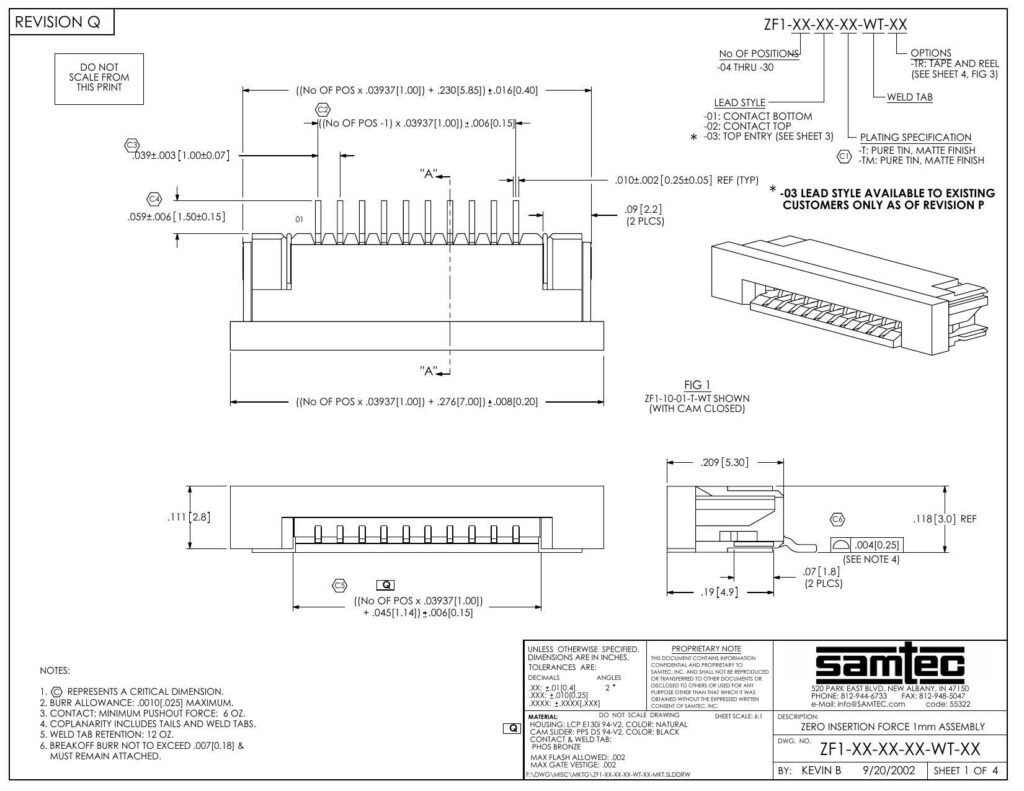
This datasheet describes the specifications and options for the Samtec Zero Insertion Force (ZIF) connector series, denoted by the part number ZFI-XX-XX-XX-WT-XX. The ZIF connector is designed for applications requiring minimal force during insertion, providing a high level of precision and durability for various electronic interfaces.
The datasheet indicates a variety of positioning options, ranging from 04 to 30 positions for connectors. The lead style of these connectors is available in three options: -01 for contact bottom, -02 for contact top, and -03 for top entry. It is important to note that the -03 lead style is limited to existing customers as of revision P. Additionally, two plating specifications are listed, which consist of pure tin with a matte finish (codes: -T and -TM).
For packaging standards, the ZIF connector is available with tape and reel options detailed on sheet 4, figure 3 of the extended datasheet. When packed, the position #1 of the connector is aligned in the same direction as indicated by the arrow on its tube. Contact pushout force and coplanarity specifications are also provided for quality assurance, with a minimum pushout force requirement of 2 oz and a burr allowance specified at a maximum of 0.010 inches.
The materials used in the construction of the connector include LCP 301 94-V0 for the housing in natural color, PPS DS 94-V0 for the assembly cam slider in black, and phosphor bronze for the contact weld tab. The part-unique contact number is defined by the last two digits of the part number after the -WT- prefix. Additionally, the datasheet instructs not to scale the drawing, emphasizing that proprietary information contained within the document is confidential and is not to be reproduced without the expressed written consent of Samtec, Inc.
The document also outlines general tolerances for decimals and angles, as well as the maximum allowable flash and gate vestige. Critical dimensions are referenced throughout, and the datasheet indicates that breakoff burr must not exceed 0.007 inches and must remain attached. Each connector variant is identified with part numbers and revision codes for traceability.
The ZIF connector series is designed by Kevin B on September 20, 2002, and the datasheet highlights contact information including Samtec’s address, phone number, fax, and email, indicating that the data sheet was created in the United States at the company headquarters in New Albany, Indiana.
Notice for Users:
All technical information found within the first two pages of the datasheet provides a comprehensive overview but not an exhaustive list of details. For full specifications, additional sheets of the datasheet or further documentation from Samtec would be required.
References:
Chat: Powered By VoiceSphere
Pricing & Distributors: https://www.datasheets360.com/part/detail/zf1-10-03-t-wt/3983456370335003129/

