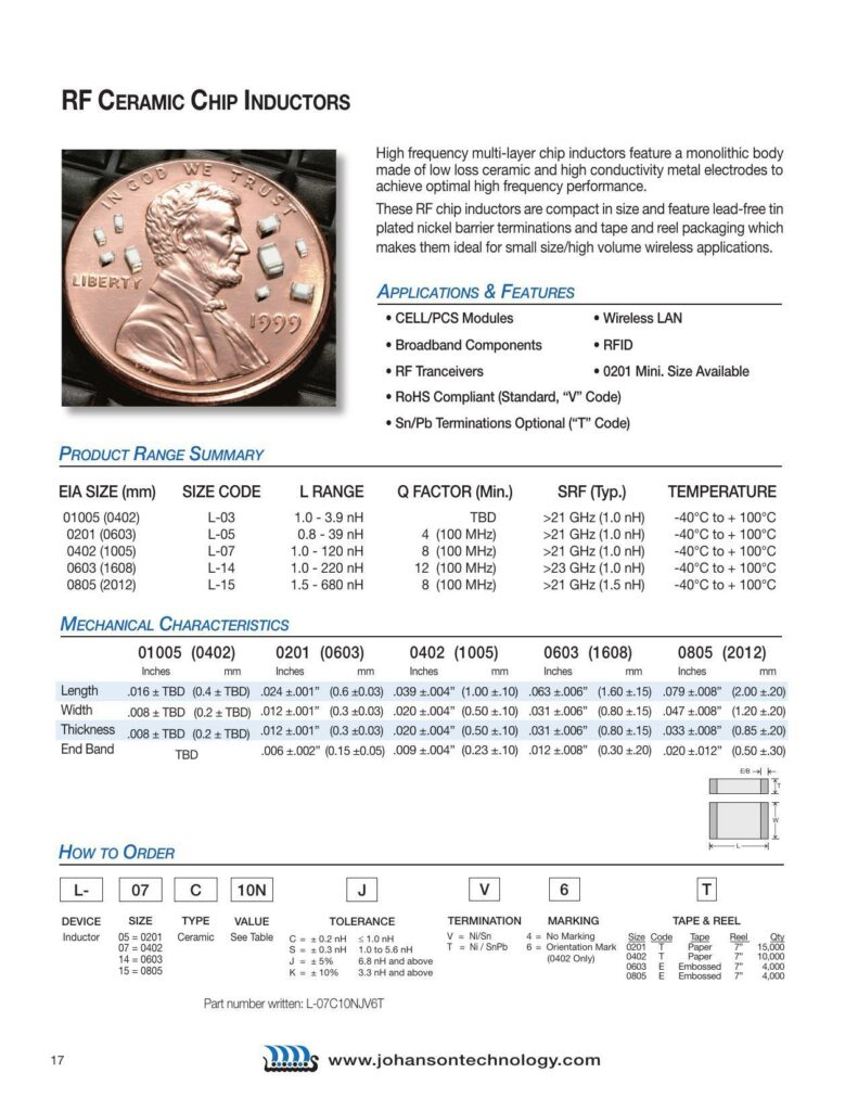
RF Ceramic Chip Inductors are high-frequency, multi-layer components utilizing low loss ceramic along with high conductivity metal electrodes to ensure superior performance for high-frequency applications. These inductors are designed to be compact, making them suitable for small size, high volume wireless applications. Examples of applications that benefit from these inductors include:
- Cell/PCS Modules
- Wireless LAN
- Broadband Components
- RFID
- RF Transceivers
Important features of these chip inductors are:
- Availability in the 0201 mini size
- Rohs Compliance with a standard “V” code
- Optional Sn/Pb terminations indicated by a “T” code
Product Range Summary
The inductors are available in a range of EIA sizes, specified in both millimeters and inches, ranging from 01005 (0402) to 0805 (2012). They come with corresponding size codes from L-03 to L-15. The inductance range varies from as low as 1.0 nH up to 680 nH, depending on the size, with quality factors (Q Factor) being minimum at certain frequencies starting from 8 at 100MHz, and self-resonant frequencies (SRF) typically above 21 GHz. These inductors can operate under temperatures ranging from -40°C to +100°C.
Mechanical Characteristics
The mechanical dimensions for each size category are outlined with length, width, thickness, and end band measurements provided in both inches and millimeters, with some values still to be determined (TBD).
How to Order
When ordering, one needs to specify the inductor size (e.g., 05 for 0201), type value (ceramic type, as per a referenced table), tolerance, and termination material. The part number is followed by a sizing code and a series of letters that denote specific product specifications. Tolerance options include ±0.2 nH for less than 1.0 nH, ±0.3 nH for 1.0 to 5.6 nH, and standard percentage tolerances for values 6.8 nH and above. Termination materials offered are Nickel/Tin (Ni/Sn) and Nickel/Lead-Tin (Ni/SnPb) options.
Marking, tape, and reel information is provided, which indicates no marking for size code, type of tape (paper or embossed), reel quantity, and reel orientation mark. For a physical example, the part number “L-O7C1ONJVGT” is provided, which encodes details such as device type, size, tolerance, termination and packaging details.
For further information, the datasheet includes a reference to the manufacturer’s website: www.johansontechnology.com, where additional details and resources about the product range can be found.
References:
Download: RF Ceramic Chip Inductors Datasheet
Chat: Powered By VoiceSphere
Pricing & Distributors: https://www.datasheets360.com/part/detail/l-07c2n2sv4t/-4772622190236025028/

