Overview
The datasheet presents the technical specifications, dimensions, and other essential details for the LFM series of LED indicators. These indicators come in different models, distinguished by their internal design features such as having a built-in resistor or not. This document contains crucial information to assist users in selecting the appropriate model for their applications.
Design and Dimensions
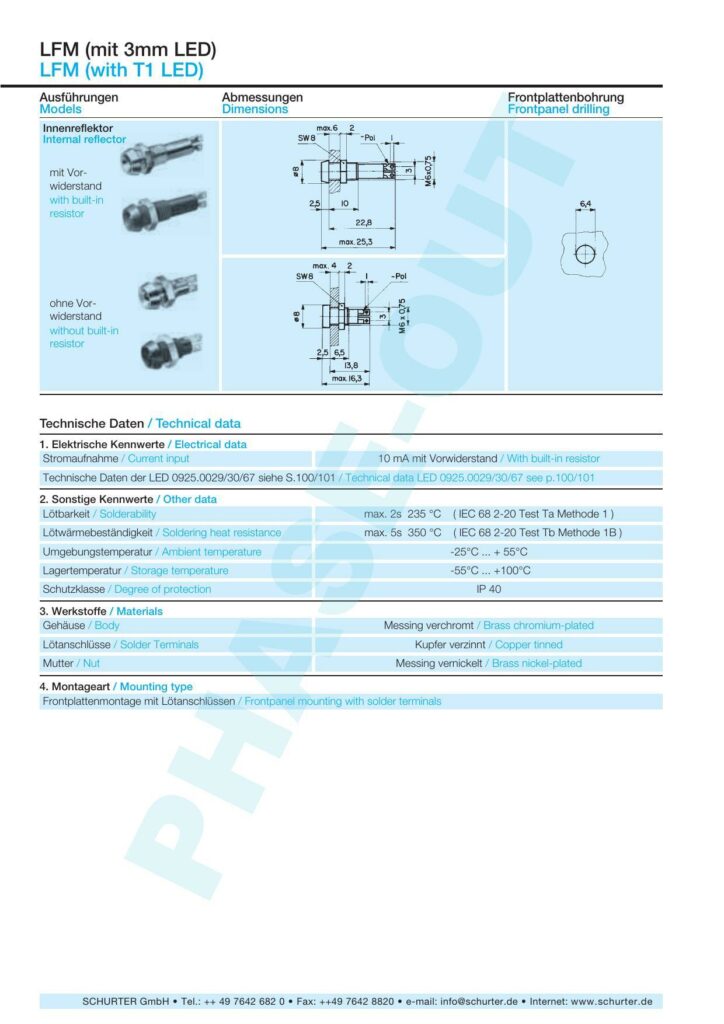
The LFM LED indicators are designed with an internal reflector and are suitable for front-panel mounting. They are available in configurations that either include a built-in resistor or exclude it. The datasheet provides detailed dimensions for the drilling size of the front panel, and maximum dimensions are outlined for the internal reflector’s depth and the overall LED indicator’s height.
With Built-in Resistor:
- Drilling diameter: 25mm
- Maximum depth (internal reflector): 25.3mm
- Spanner size: SW8
Without Built-in Resistor:
- Drilling diameter: 25mm
- Depth: 6.5mm to a maximum of 16.3mm
- Spanner size: SW8
Technical Data
Electrical Characteristics
The LFM LED indicators with a built-in resistor have a current input of 10 mA. For comprehensive details on the electrical data of the LED component, reference is directed to pages 100 and 101 of the datasheet.
Other Specifications
The solderability of the LED indicators is confirmed to handle a maximum of 2 seconds at 235°C according to IEC 68 2-20 Test Ta Method 1, and the soldering heat resistance is capable of tolerating up to 350°C for a maximum of 5 seconds as per IEC 68 2-20 Test Tb Method 1B.
These indicators are designed to operate within an ambient temperature range of -25°C to 55°C and can be safely stored at temperatures up to 100°C. The degree of protection is rated at IP 40, indicating a basic level of protection against solid objects.
Materials and Assembly
The body of the indicators is constructed with brass chromium-plated, offering durability and a polished finish. The solder terminals are made of tinned copper, while the nut is composed of nickel-plated brass. Suitable for front-panel mounting, these indicators are designed to be assembled with solder terminals.
Contact Information
For further information or assistance, contact SCHURTER GmbH is provided, including their phone number, fax, email, and website.
References:
Download: LFM Series LED Indicators Datasheet
Chat: Powered By VoiceSphere
Pricing & Distributors: https://www.datasheets360.com/part/detail/0035-0721/4530995453900865806/

