Overview of Corning Gilbert GPO Male Flange Mount Connectors
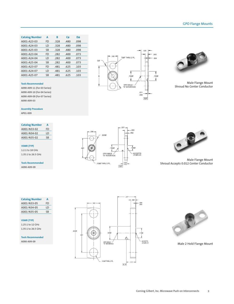
The datasheet provided outlines the specifications for GPO Male Flange Mount Connectors, which are part of Corning Gilbert, Inc.’s Microwave Push-On Interconnects product line. These connectors are designed for high-frequency applications, with models supporting frequencies from 12 GHz up to 26.5 GHz. The datasheet lists various catalog numbers for different series of these connectors, such as A001-A23-03 FD, AO01-A24-03 LD, AO01-A25-03 SB, and others, each tailored for specific interconnect requirements.
Key Specifications
The connectors are described by their Voltage Standing Wave Ratio (VSWR), which is a measure of how effectively the connector is transferring radio frequency power. Typical VSWR values provided by the datasheet range from 1.25:1 to 1.35:1 over the specified frequency ranges. These values suggest high-quality connectors with minimal signal reflection, which can be critical for maintaining signal integrity in microwave systems.
Design Features
The connectors are detailed with a GPo Male “A” interface, ensuring compatibility with standard microwave components. Some variants, like the Male Flange Mount Shroud, are available with or without a center conductor, providing flexibility for different assembly requirements. For connectors that accept a center conductor, the datasheet indicates that 0.012 diameter center conductors are accommodated.
Installation Tools
To assist in the proper assembly of these connectors, the datasheet recommends specific tools for each series. For the -03 series, the recommended tool is A090-A99-11, while the -04 series should be assembled using tool A090-A99-10, and the -07 series with A090-A99-09. An additional tool, A090-A99-03, is also listed without specifying the applicable series.
Physical Characteristics
The physical dimensions specified include the flange size, with the datasheet providing flange dimensions such as 0.400 inches through 0.625 inches for some models, and 1.030 inches through flanges for other models. Furthermore, the connectors are categorized by catalog number and each features an indication of whether it has a Full Detent (FD), Limited Detent (LD), or Smooth Bore (SB) configuration, which affects the mechanical connection and ease of mating with other components.
Assembly Instructions
Assembly procedures are available under document APO1-009, which is referenced but not detailed in the datasheet. Those seeking to assemble the connectors properly should consult this document for complete instructions.
The datasheet’s focus on GPO Male Flange Mount Connectors is central for engineers and technicians looking for reliable interconnect solutions for their high-frequency communication systems. With a comprehensive selection of configurations and the support of precise assembly tools, Corning Gilbert positions these connectors as essential components in radio frequency applications.
References:
Chat: Powered By VoiceSphere
Pricing & Distributors: https://www.datasheets360.com/part/detail/a001-a23-03/3227196699455738728/


