Overview of FC Series Fiber Optic Connectors
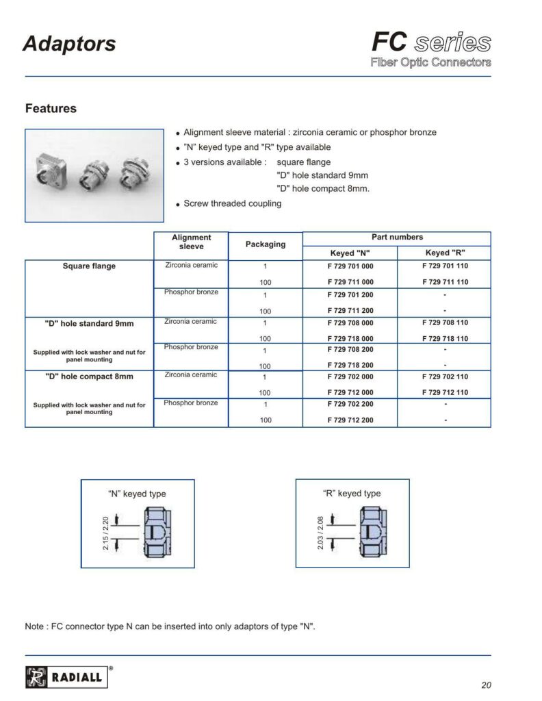
The FC series of Fiber Optic Connectors are designed with a focus on reliability and performance. These connectors feature alignment sleeves made from either zirconia ceramic or phosphor bronze, which are essential components for ensuring fiber alignment and optimal signal transmission. The datasheet provides an exhaustive list of part numbers, indicating a variety of connectors within the series are available to suit different needs.
Connectors and Key Features
There are several key characteristics of these fiber optic connectors described in the datasheet:
– Connector Types: The FC series includes both “N” keyed and “R” type connectors, allowing for compatibility with different fiberoptic systems based on the keying configuration.
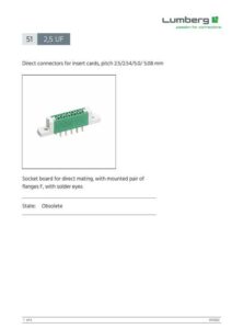
– Flange Versions: The connectors come in two flange versions: a standard square flange and a “D” hole flange that is available in either a 9mm standard size or a compact 8mm size.
– Coupling: A threaded screw coupling mechanism provides secure attachment.
– Packaging: The connectors are supplied in packages of 100 with lock washers and nuts for panel mounting, ensuring that users have the necessary hardware for installation.
Part Numbers and Ordering
The datasheet lists detailed part numbers for quick and precise ordering. Buyers can find the exact part they need by referring to the provided part numbers according to the following categories:
– Keyed Type: Each keyed type, either “N” or “R,” has unique part numbers for various configurations.
– Sleeve Material: Choices between zirconia ceramic or phosphor bronze for the alignment sleeves are available.
– Flange Type: Depending on the application’s requirements, one can select from square flange parts or choose between standard or compact “D” holes.
Important Compatibility Note
It is particularly noted that the “N” keyed type FC connectors can only be used with corresponding “N” type adaptors, which is a critical compatibility consideration for system integrators and network designers.
Physical Specifications
While only a preview of the dimensions is provided, the datasheet hints at detailed dimensional information for the connectors. The square flange and “D” hole 9mm size are specifically mentioned, with a reference to conversion metrics for millimeters to inches (1 mm = 0.03937 inches). These details are essential for engineers and technicians to ensure proper fitment into their designs or matching existing infrastructure.
RADIALL, the manufacturer, provides this information likely on subsequent pages for those needing precise measurements. However, the mentioned conversion factor allows for a quick estimation if needed.
References:
Chat: Powered By VoiceSphere
Pricing & Distributors: https://www.datasheets360.com/part/detail/f729702200/9036297765953093556/