Introduction
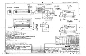
The provided content appears to be from a datasheet related to a lead-free solder electronic component used for printed circuit board (PCB) assemblies. It contains technical specifications regarding the component’s physical dimensions, electrical characteristics, and other relevant information that would inform users about its proper application and usage.
Physical Features
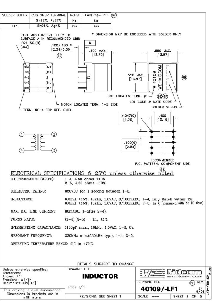
In terms of physical construction, the component must fit precisely into the recommended grid dimension of 0.021 squared (over nine positions) [453] with a tolerance of 100/.130 [2.54/3.30] millimeters. The datasheet stipulates that in certain cases, dimensions may be exceeded with solder alone. Furthermore, reference dimensions are provided for terms, notably TERM. NO:’s, which are only for reference and not indicative of actual terminal numbers.
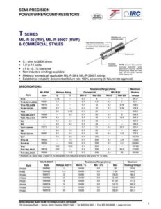
ELECTRICAL SPECIFICATIONS
Electrical Properties
Important electrical properties are listed, such as direct current (D.C.) resistance, which is specified at 4.50 ohms ±10% for both 1-4 and 2-5 terminal pairings. The dielectric rating is stated at 850VDC for one second between terminals 1-2. Regarding inductance, it is detailed at 6.0mH ±15% at 10kHz with a 1.0VAC signal, without DC casing, for both 1-4 and 2-5 terminal combinations. Noteworthy is that the inductance should match within 1% for specified terminal pairings. The maximum direct current (DC) line current capacity is denoted as 80mA DC, between terminals 1-5 (assumed to be the combination of terminals 2 and 4).
Other Specifications
A turns ratio of 1:1 ±1% is mentioned for terminals (1-4) to (2-5). The component’s interwinding capacitance should not exceed 1150pF at 10kHz and 1.0VAC between terminals 1-2. The resonant frequency is given as a minimum of 220kHz, with a typical value of 530kHz, across terminal pairs 1-4 and 2-5. The operating temperature range is from 0°C to +70°C, which indicates the range within which the component’s performance is guaranteed.
Component Identification and Reference
Additional details such as terminal identification, lot code, and date code placement are also featured. The document points out the position of dot notch locating TERM 1-5 on the component’s side. A table or a grid pattern may be included, possibly to illustrate the recommended PCB pattern for mounting the component.
Regulatory Compliance
The sheet emphasizes compliance with RoHS (Restriction of Hazardous Substances) regulations by marking the electronic component as lead (Pb)-free using Sn96%, Ag4% solder. Information on various lead-based and lead-free solder compositions is included, alongside corresponding solder suffixes for customer terminal labeling and whether these compositions meet RoHS compliance.
Document Reference
It is indicated that the drawing is dual-dimensioned, with dimensions in brackets provided in millimeters for global compatibility. A drawing title, “INDUCTOR,” suggests that the component is an inductor. Further details about revisions, drawing number, and date are given, possibly to guide version control and manufacturing tasks. For instance, the drawing number (40109/-LF1), revision letter (6F), and date (9/06) are specified, alongside a URL referring to the manufacturer’s website, www.midcom-inc.com. Lastly, tolerances for angles, fractions, and decimals are provided, giving the precise requirements for fabrication.
References:
Download: Datasheet Analysis of an Electronic Component
Chat: Powered By VoiceSphere
Pricing & Distributors: https://www.datasheets360.com/part/detail/40109/-7073618108838599425/