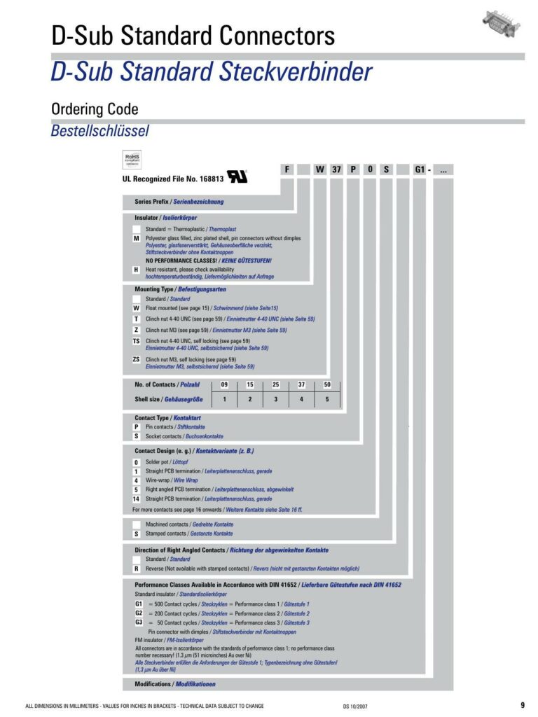
Overview of D-Sub Standard Connectors
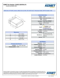
This datasheet provides detailed information on D-Sub standard connectors, recognized under UL File No. 168813. The primary specifications include the insulator made of standard thermoplastic polyester, glass-filled, with a zinc-plated shell. Various mounting types and contact designs are described, such as float mounted, clinch nuts, wire-wrap, and right-angled or straight PCB terminations.
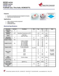
Materials and Specifications
The document details the mechanical and electrical data for the connectors. Key mechanical specifications mention mating and unmating force per signal contact, with mating force being less than 3.4N and the unmating force stated as 0.2 N. The maximum torque is 40 Ncm (0.295 ft.lb). For electrical data, the connectors have a current rating of 5 A at room temperature and a test voltage rating between contacts of 1200 V for 1 minute. They also meet transition resistance requirements as per DIN 41652 and feature an insulation resistance between contacts of 5000 MΩ and volume resistivity of 106Ω cm, with a dielectric strength of 50 kV/mm.
Design Features and Performance
Contact type options are pin or socket contacts, with designs for solder pot, straight PCB, and wire-wrap, among others. Performance classes are available in accordance with DIN 41652, with standard insulators rated for up to 500 contact cycles. Additionally, modifications to shell, insulator materials, and environmental compliance are indicated, highlighting features such as heat resistance and compliance with various standards like UL94V-0.
Materials, Plating, and Environmental Compliance
Materials used include steel shell housing, and different plating options are provided, such as tin plated over nickel and yellow chromate over zinc. The connectors come with a variety of temperature thresholds depending on the chosen material. Notably, there are some options not compliant with RoHS, specifically the yellow chromate over zinc plating.
Construction and Contact Options
Connectors are made using machined or stamped contacts, indicating a choice between durable and more economical options. The direction of right-angled contacts can be standard or reverse, with the latter not available for stamped contacts.
Additional Notes
All dimensions are provided in millimeters with values for inches in brackets, and the technical data is subject to change without notice. Special attention should be paid to the suitability of connectors for locking screws and the specific requirements for environmental resilience and mechanical endurance.
References:
Chat: Powered By VoiceSphere
Pricing & Distributors: https://www.datasheets360.com/part/detail/f09p4g1/-8349264357711236677/