Summary of KEMET Ceramic Chip Capacitors
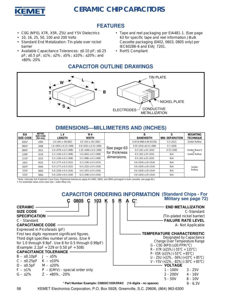
The first two pages of the datasheet provide an overview of KEMET’s Ceramic Chip Capacitors, their features, specifications, and ordering information. The capacitors are designed with various dielectric materials labeled as COG (NPO), XZR, XSR, ZSU, and YSV, suitable for different temperature ranges and stability requirements.
Features and Packaging
The capacitors come in tape and reel packaging compliant with the EIA481-1 standard, which is detailed on other pages within the datasheet, and also in bulk and cassette packaging for select sizes (0402, 0603, 0805). Bulk capacitance tolerances range from +0.10 pF to +80% / -20%, ensuring a broad spectrum of precision for various applications. The capacitors are RoHS compliant and feature standard tin-plated nickel barrier end metallization, which enhances their solderability in reflow and wave soldering applications.
Capacitor Outline Drawings and Dimensions
Outline drawings with millimeter and inch dimensions are provided for a range of capacitor sizes. Key dimensions highlighted include the length (L), width (W), and mounting bandwidth (minimum separation). Specific sizes come with indulgences such as solder reflow capability, which is detailed on a separate page. The tables list dimensions for a series of named capacitor sizes according to both EIA (Electronic Industries Alliance) and metric size codes. Notably, certain case sizes are recommended by EIA, with tightened tolerances for devices packaged in bulk cassette.
Ordering Information
Ordering information for ceramic chip capacitors is presented in the form of an identifier code which includes details such as size code, capacitance, capacitance tolerance, voltage rating, and temperature characteristic. The capacitance code is expressed in picofarads and may incorporate leading digits for significant figures and a third digit to indicate the multiplier (number of zeros). The temperature characteristic is denoted by a letter code representing the dielectric material and its corresponding change over the temperature range.
The summary addresses the specifics of the COG (NPO) characteristic, with a temperature coefficient of approximately +30 PPM/°C, and other temperature characteristics for the XZR, XSR, ZSU, and YSV dielectrics which offer different percentage changes across specified temperature ranges. This temperature characteristic is a critical specification for selecting the proper capacitor for temperature-sensitive circuits.
Capacitance tolerance is another key specification denoted by various letter codes, ranging from tight tolerances (for example, +0.10 pF or +5%) to broader variances (such as +80% / -20%). The voltage rating of the capacitors is also specified, with options listed including 10V, 16V, 25V, 50V, 100V, and 200V, allowing users to select the appropriate voltage rating for their application requirements.
The provided example part number “C0805C103KSRAC” serves as an aid for understanding how to construct a capacitor’s 14-digit identifier based on the required specifications with no spaces.
Manual:
Chat: Powered By VoiceSphere
Pricing & Distributors: https://www.datasheets360.com/part/detail/c0402c124m9pac/-6723501041710834393/

