Overview
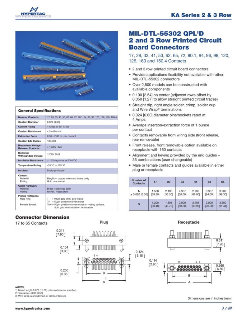
The KA Series MIL-DTL-55302 QPL’D 2 and 3 Row Printed Circuit Board Connectors provide a range of connector models designed for printed circuit boards (PCBs), with a special focus on flexibility to meet various application needs. Featuring straight dip, right angle solder, crimp, solder cup, and Wire Wrap terminations, the connectors facilitate effective electrical connections in high-density electronic components.
Features
The connectors are available in various model configurations, with over 2,500 models possible through different component combinations. The series offers connectors with 17 to 160.4 contacts in both male and female variations. They are designed with a 0.100 [2.54] pitch spacing, with adjacent rows offset by 0.050 [1.27] to enable straight printed circuit traces. Additionally, the connectors come with 0.024 [0.60] diameter pins/sockets capable of supporting a rated current flow of Amps at a temperature rise of 30°C.
Technical Specifications
The contact resistance is specified as milliohms, while the insertion and extraction force average between 0.30 and 2.00 ounces per contact. The connectors support up to 100,000 contact life cycles and can withstand breakdown voltages of 1600 V RMS. They also have a dielectric withstanding voltage of 1200 V RMS and an insulation resistance of 10^6 Megohms at 500 VDC. Temperature tolerance for the series ranges from -55°C to +125°C.
Materials and Plating
Insulators for the KA Series are composed of diallyl-phthalate, while the contact materials include beryllium copper wires and brass bodies. The connectors come with gold over nickel plating, with additional plating specifications for male pins and guides, including options for 10 uin gold (min) over nickel and 50 uin gold (min) over nickel plating.
Dimensions
Dimensions of both plugs and receptacles vary according to the number of contacts—from 17 to 65—and are provided in both inches and millimeters. More specific dimensions such as connector heights, lengths, and widths are detailed alongside notes regarding mated length and tolerance, with the mated length being 0.622 [15.80] inches unless specified otherwise. Tolerances are noted at 0.02 [0.50] inches. The datasheet specifies that the term ‘Wire Wrap’ is a trademark of Gardner Denver.
For more detailed information about the connectors or technical support, the hyperlink ‘www.hypertronics.com’ is included toward the bottom of the second page, indicating the company’s comprehensive website.
References:
Download: MIL-DTL-55302 QPL’D 2 and 3 Row Printed Circuit Board Connectors – KA Series
Chat: Powered By VoiceSphere
Pricing & Distributors: https://www.datasheets360.com/part/detail/ka17-127bpmc10th/2879417277011177310/

