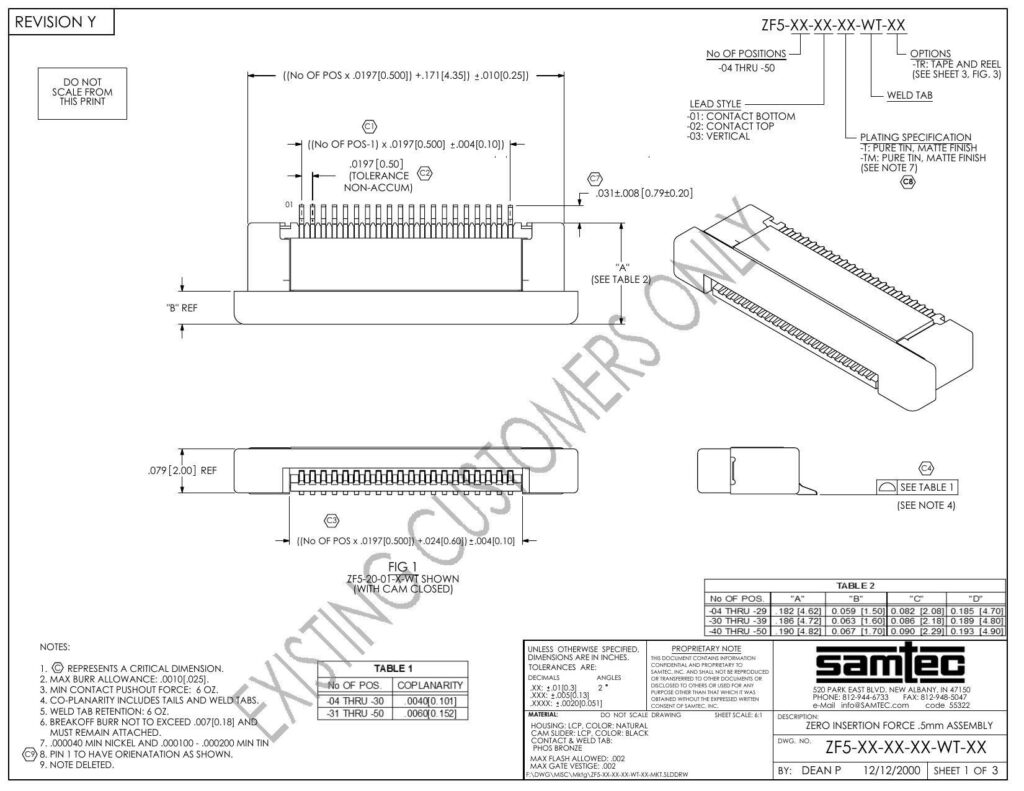
The datasheet with the revision label Y describes the specifications for a Zero Insertion Force (ZIF) connector, part number ZFS-XX-XX-XX-WT-XX. This connector is available with a variable number of positions, specifically in a range from 4 through 50. It highlights different options for ordering, such as tape and reel packaging denoted by the option code ~TR, as detailed on sheet 3, figure 31 of the datasheet. Additionally, two significant measurements are provided for positional calculation: the distance between positions is .0197 inches (0.500 mm), and the length added per number of positions is provided in a formula taking into account the number of positions and the standardized additional length.
Key features of this ZIF connector include options for the lead style such as ~01 for contact at the bottom, ~02 for contact at the top, and ~03 for a vertical lead orientation. Plating specifications are cited as TFPURE with a Tin Matte finish or -TM. Note 7 likely contains important information regarding plating specifics.
Dimensions provided in the datasheet are listed in inches, with dual measurements frequently provided in brackets to indicate millimeter equivalents. Dimensional tolerances are detailed with specified accuracies for decimal and angle measurements. The coplanarity for the number of positions is detailed in Table 1, which shows different specifications for groups of connectors ranging from 4 through 30 positions and from 31 through 50 positions.
The materials used for various components of the ZIF connector include a natural-colored LCP (liquid crystal polymer) for the assembly and a black-colored CP (presumably another type of thermoplastic) for the cam slider. The contact and weld tab of the connector is made from phosphor bronze. The datasheet also mentions a maximum flash allowance and a maximum gate vestige, indicating tolerance for excess materials in the molding process.
Additional specifications note the minimum contact pushout force, weld tab retention, and orientation for the pins, as well as a maximum burr allowance for a breakoff burr, which must remain attached. The drawing also specifies the minimum nickel underplate and tin plating thickness to ensure durability and electrical conductivity.
The datasheet features reference numbers and dimensional guidelines visualized in representative drawings and tables. The customer is advised not to scale the drawing and to refer to specific notes and tables for further information, with an emphasis on Note 4 and Table 2, which appear to contain critical dimensional details. Furthermore, the document contains proprietary information, emphasizing that consent from Samtec, the manufacturer located in New Albany, Indiana, is required for reproducing or transferring the document’s information.
References:
Download: ZFS-XX-XX-XX-WT-XX Datasheet
Chat: Powered By VoiceSphere
Pricing & Distributors: https://www.datasheets360.com/part/detail/zf5-20-03-t-wt-tr/6428542940332346006/

